RAM Test
In 1973 this test was called WORSE CASE TEST. It was specifically designed for the core memory module. The software generated an alternate ‘0’ and ‘1’ pattern in sequential physical locations of the processor’s memory core mat. This procedure requires precise knowledge of the relationship between logical and physical memory layout. The old name clashed with the WORST CASE TEST of the calibration procedures. So I’ve renamed it to RAM Test.
I’ve also extended the test in the USB Interface for various more patterns. This allows a more intensive test of the semiconductor memory modules. The RAM configuration is automatically detected during this test. In case of an error, the faulty IC identifiers are shown on the screen.
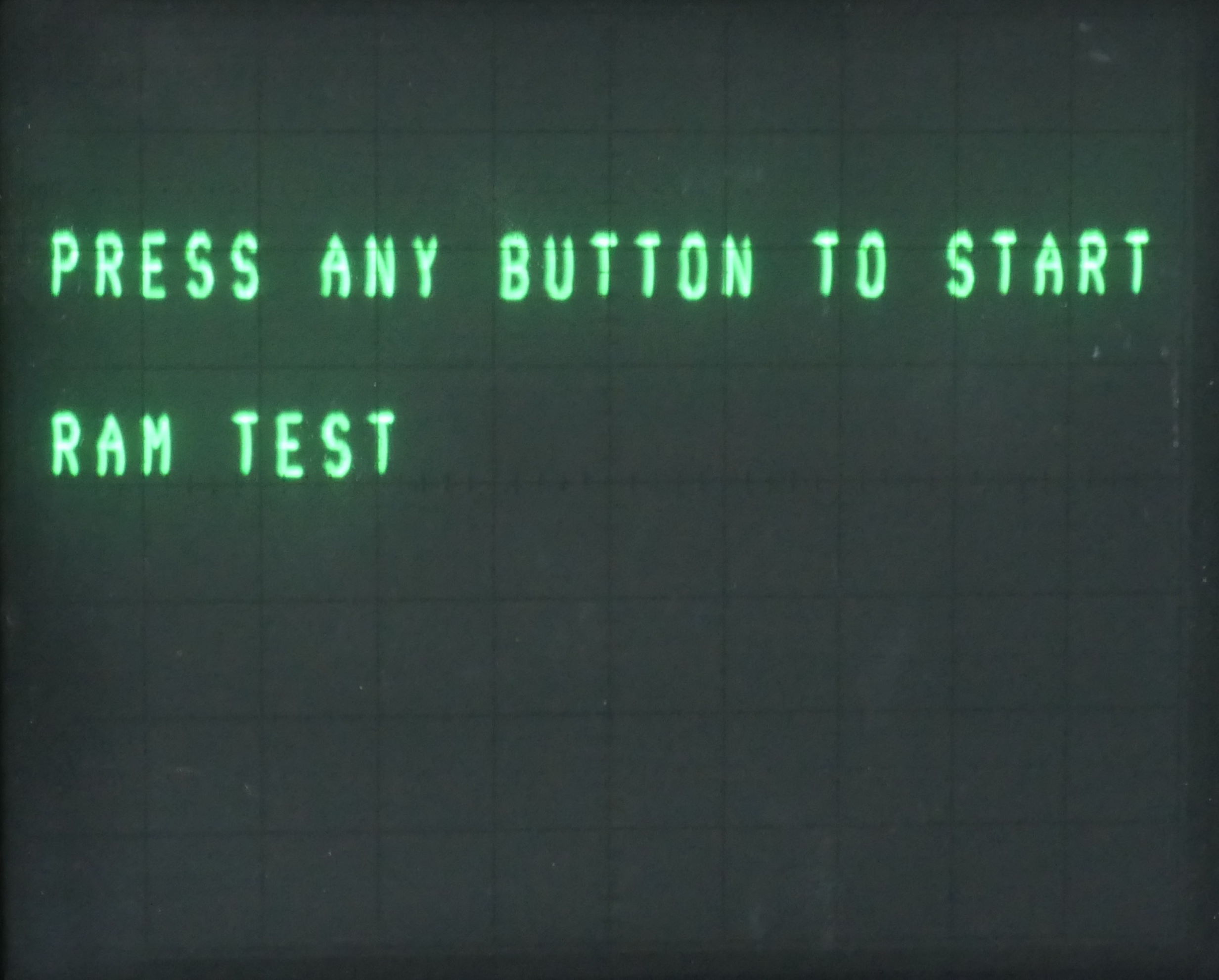
Instructions for the RAM test
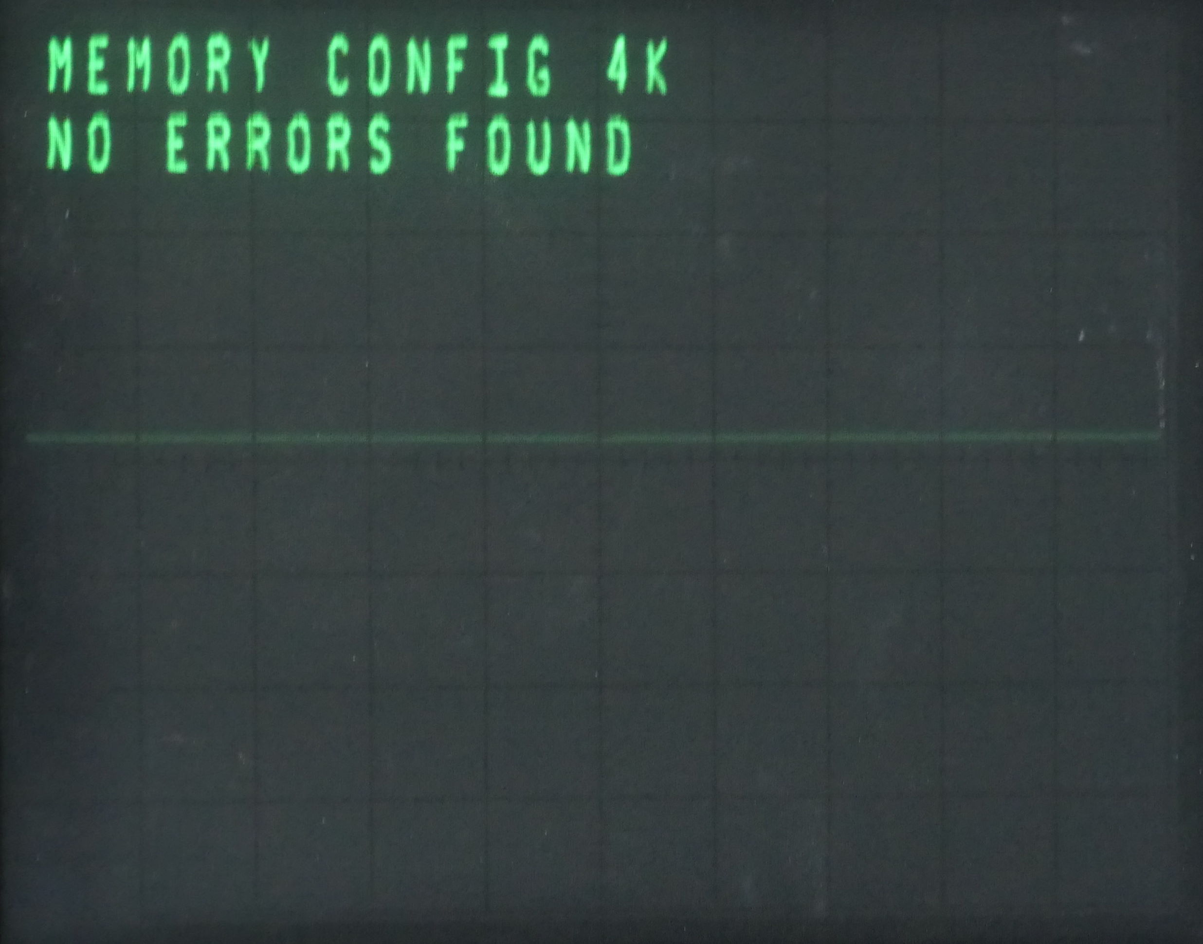
Regular output of the RAM test. The memory board configuration was detected as 4k. No errors were found.
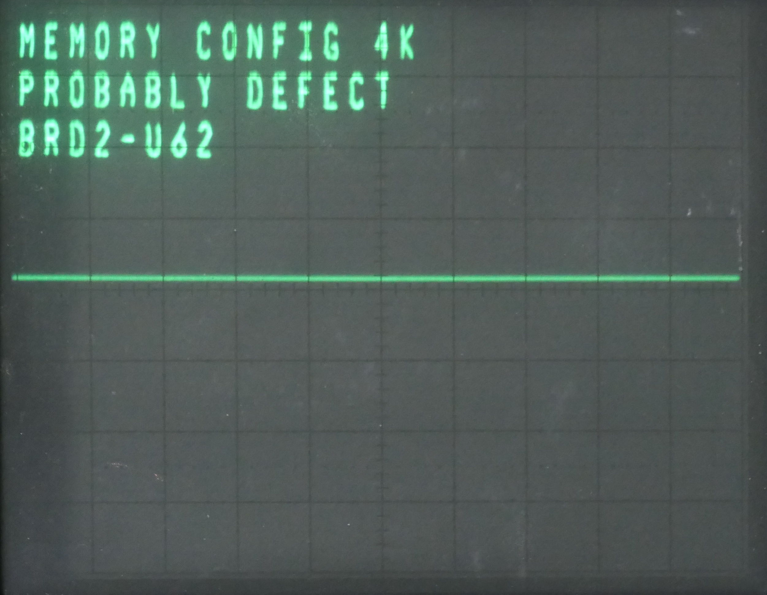
Example output of the RAM test in case of an error. The board number and faulty IC Id displayed. The output messages are only correct if the jumpers on the RAM cards are in the default factory positions. It’s also impossible for the firmware to recognize whether a core memory or a semiconductor memory module is installed. So it’s up to the user to interpret the message.
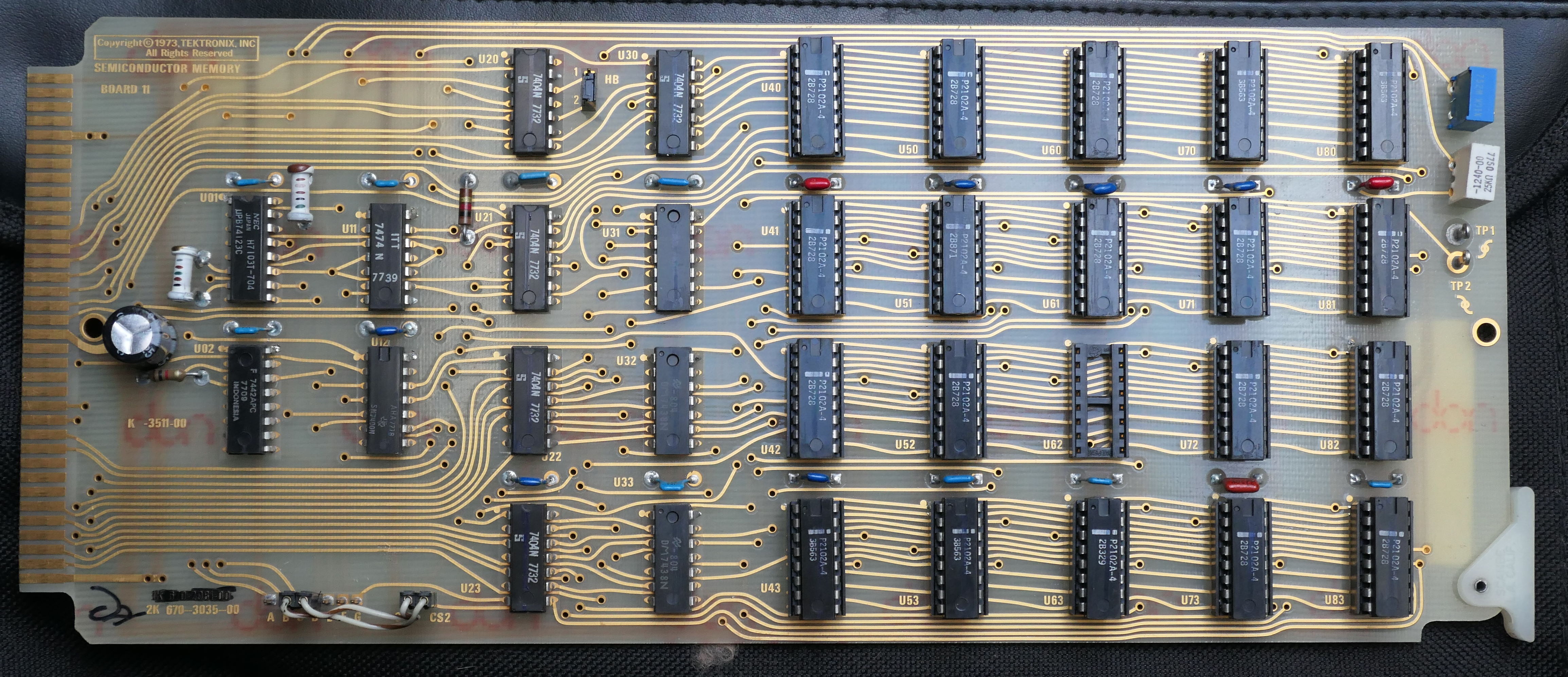
This board produced the error message above. Maybe you can spot the reason for the error…