Yellow Program Card
One intended purpose of the USB Interface is to demonstrate the capabilities of the P7001 at the vintageTEK museum or any other collection. The demonstration should be simple enough to be understood by a typical visitor of the museum.
Original card
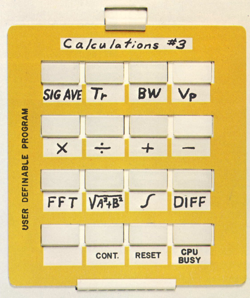
This yellow user definable program card was shown in many DPO advertisings and other publications of 1973. It showed in a very simple way the programmable capabilities of the system.
The card was actually a pre-production card. The final design of the blank yellow card can be seen here: Overlay cards
Modern recreation
I think using a yellow program card for the demo would be a perfect reminder of the past. So I’ve designed a new one and ordered some samples.
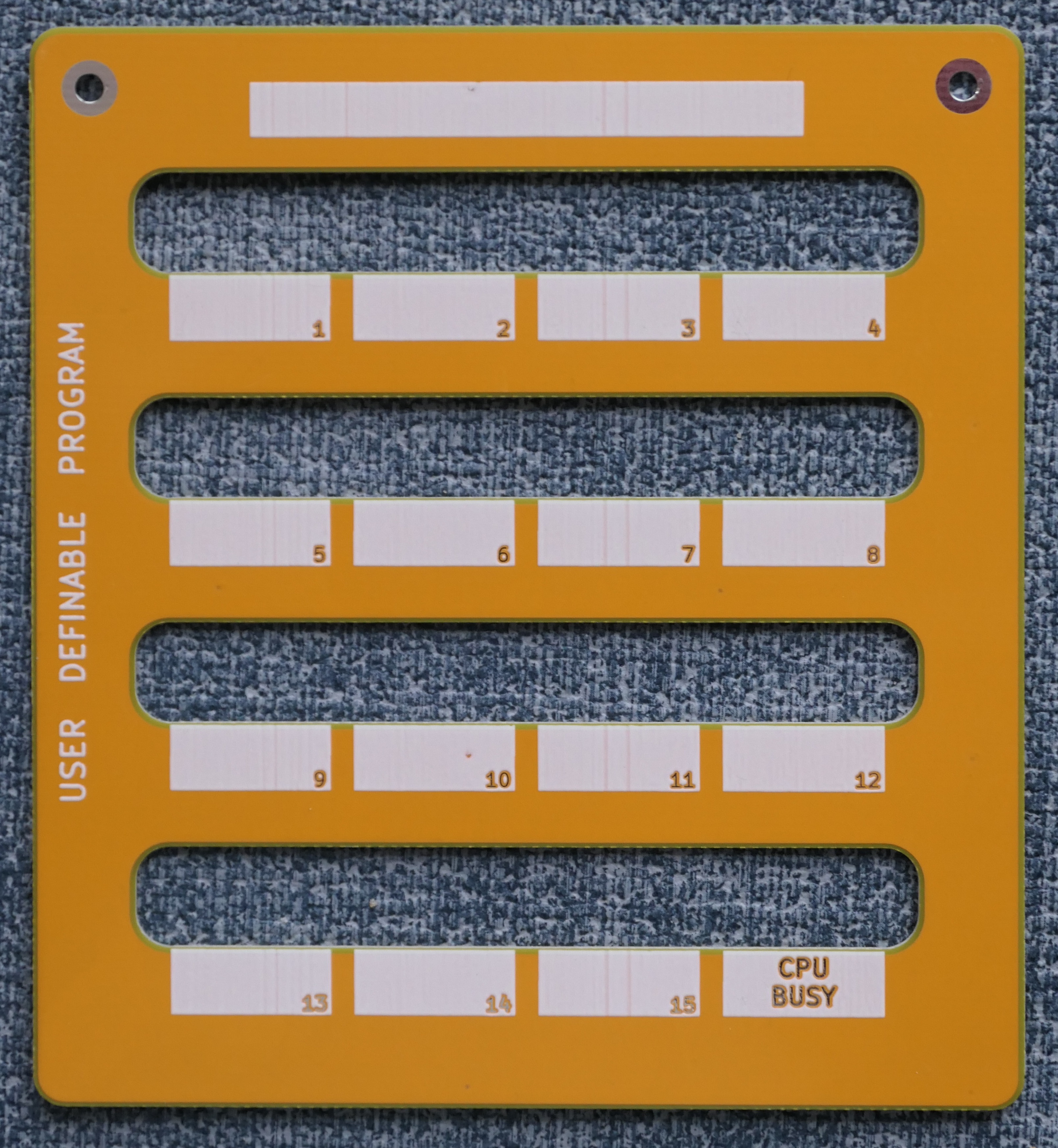
Apparently the manufacturer of the new card has a slightly different understanding of “yellow”…
I haven’t finished the demonstration program yet. The following paragraphs only reflect the current state of the development.
Signal Averaging
Signal averaging can be used to extract repetitive signals out of a noisy background.
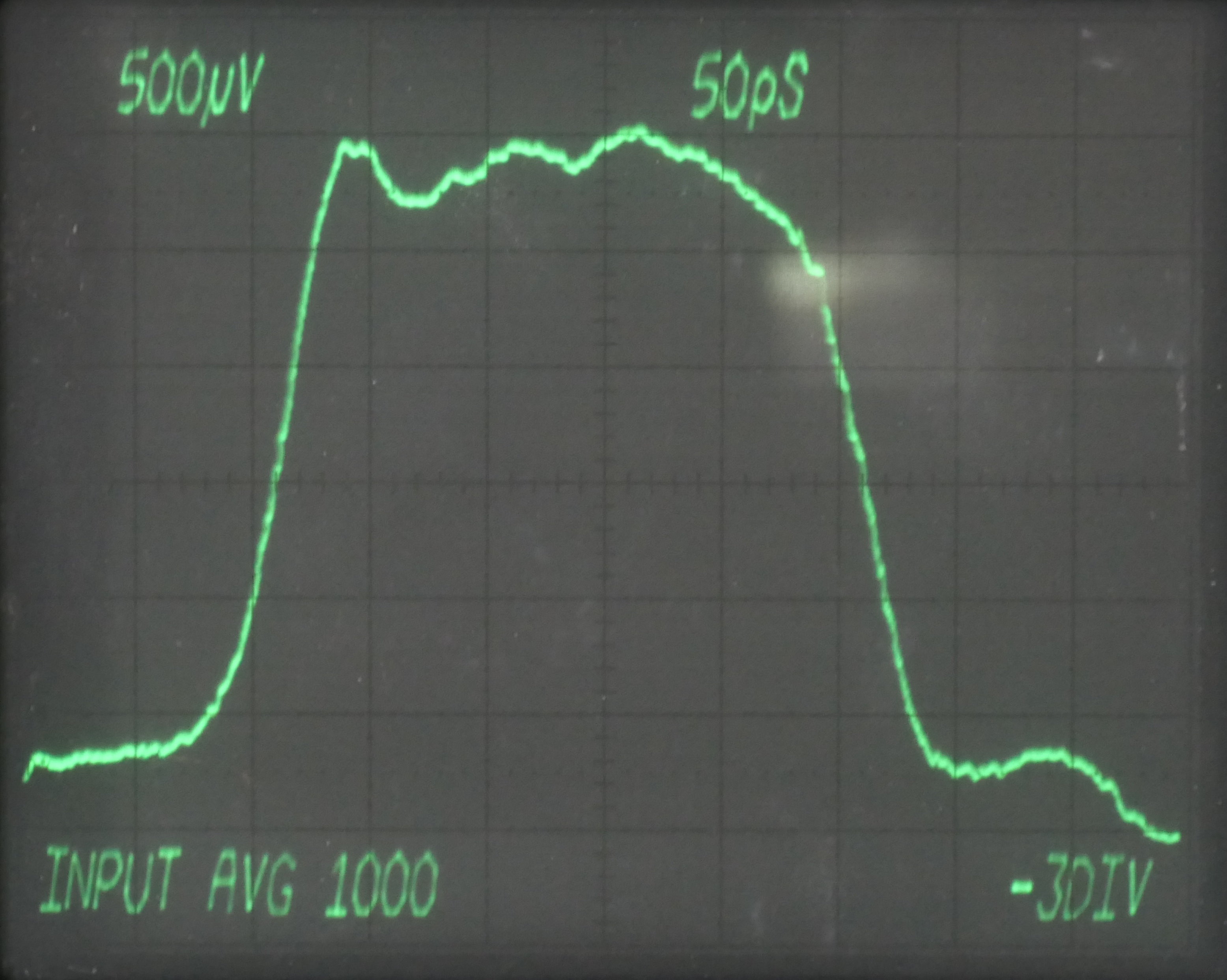
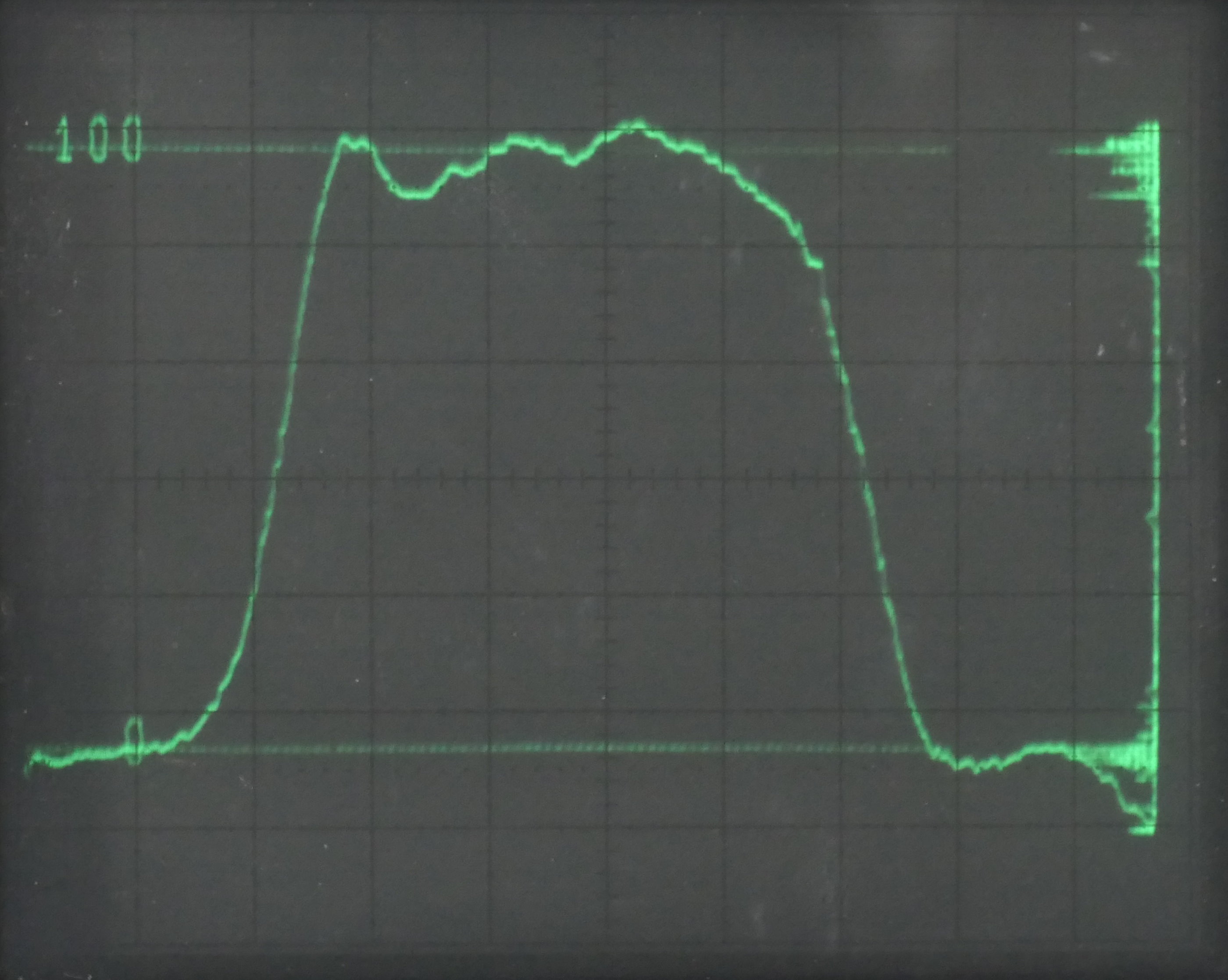
Waveform Envelope
The envelope command was added in late 1977 as an optional program to the DPO. It can be used to monitor variation limits of a signal.
Histogram
A histogram is essential to be able to calculate most of the waveform parameters. The animated demo shows how a histogram is calculated from the waveform data.
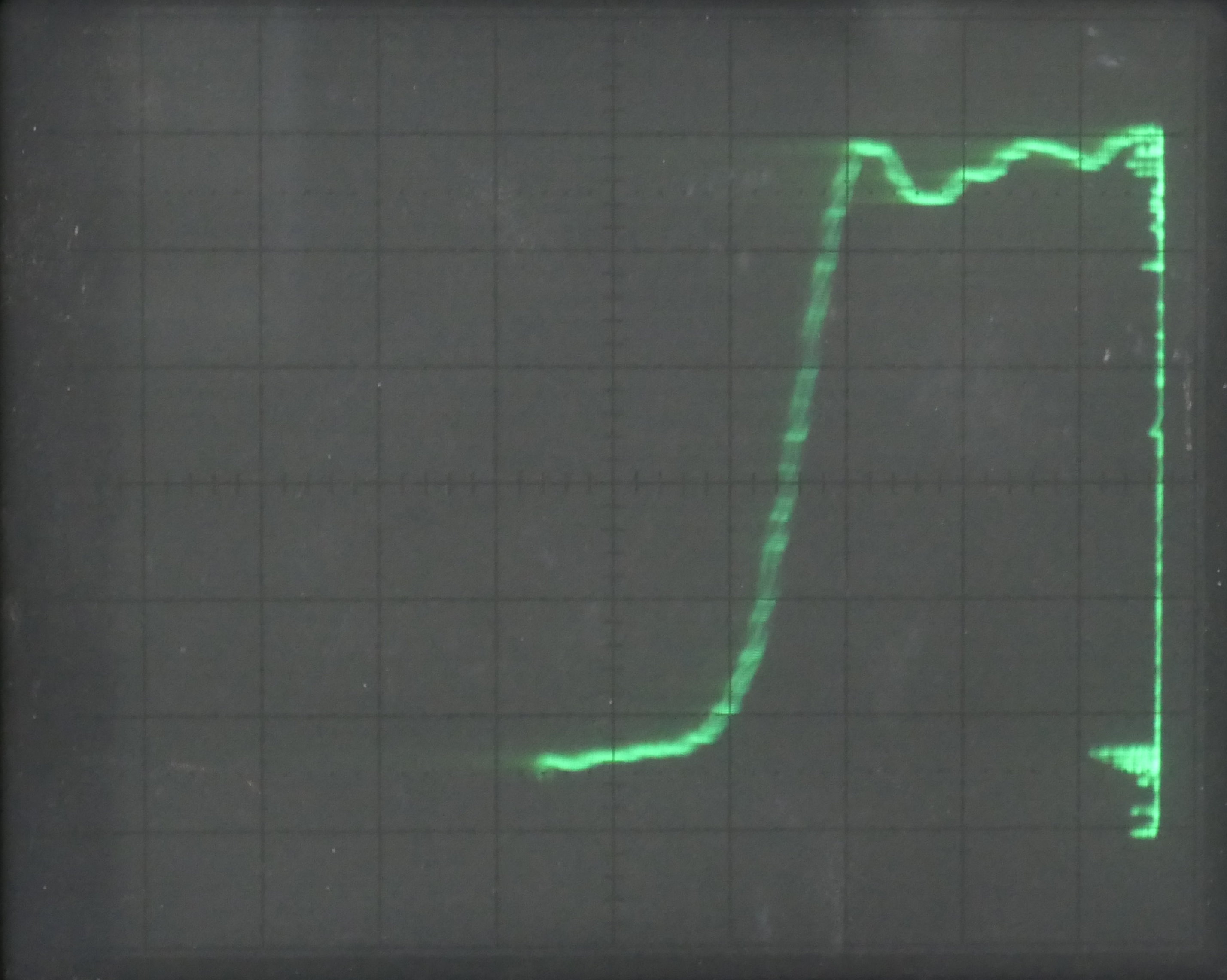
The digitized signal is moved slowly to the right edge of the screen. The individual waveform points stack up and create a vertical histogram…
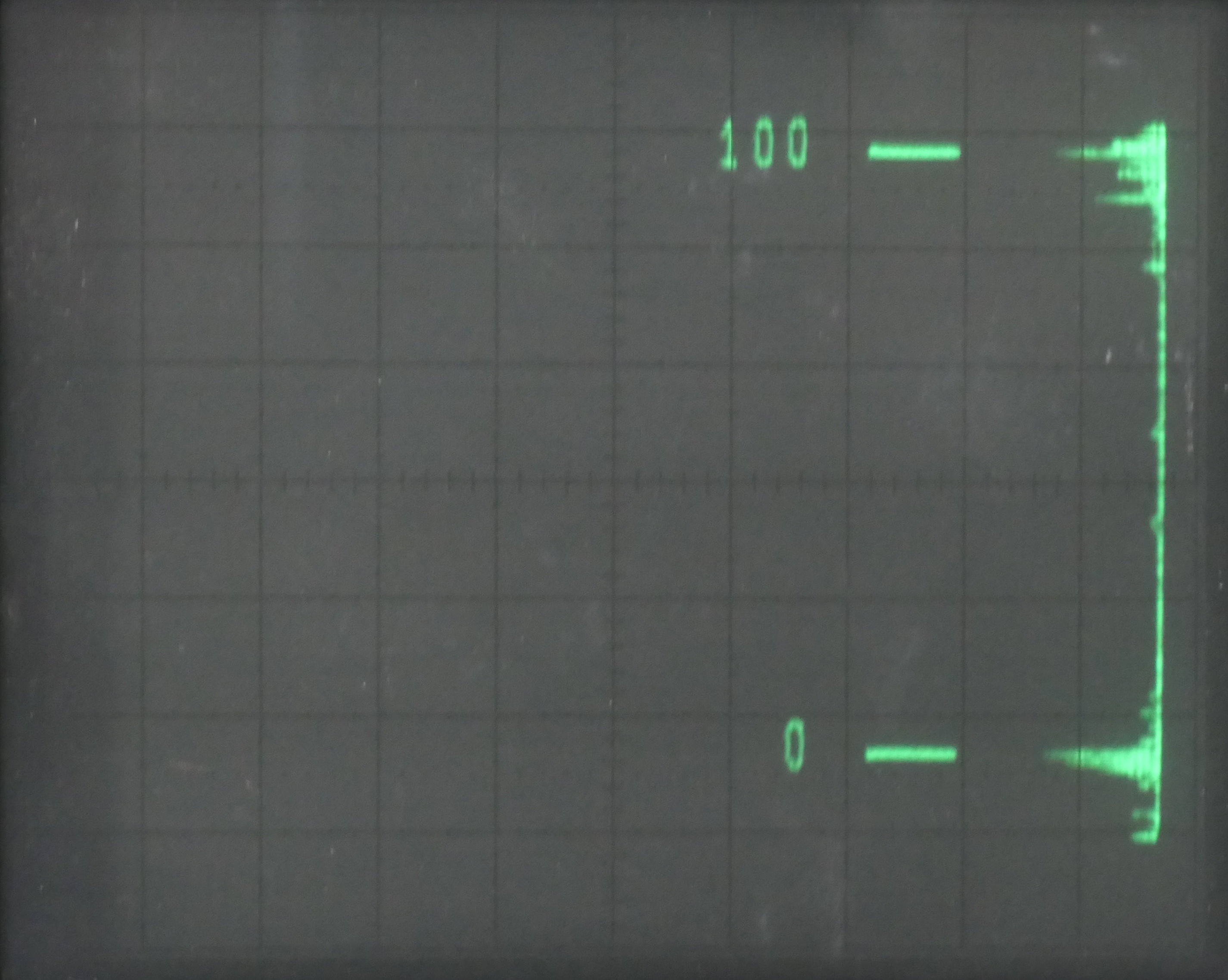
The highest horizontal slots define the 0% and 100% levels of the waveform. The waveform then moves back to the original position.
A short video can be found here.
Waveform Parameters
Based on the histogram several waveform parameters can be calculated. Actually, the program provides the values for Min, Max, P-P, Energy, Rise- & Falltime, Delay and Duration.
A short video can be found here.
FFT
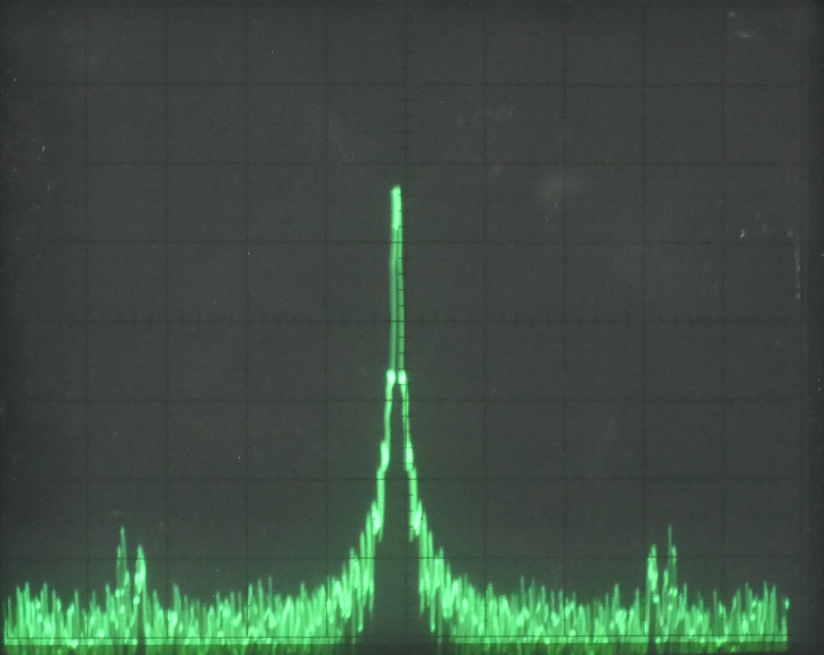
The FFT demo was an idea to show the mathematical capabilities of the Teensy 4.1 module. The FFT of the input signal was calculated in real time. But then we discovered that the average visitor will not understand the output. So we decided to remove the FFT demo.
A short video can be found here.