Terminal
The Teensy 4.1 USB development board provides a native USB interface that can operate at up to 480 Mbit/sec. This interface is used by the P7001 USB Interface to communicate with a modern computer. No drivers are needed. The interface is automatically detected as a COM-port on Windows 7 or newer. Baud rate settings are ignored - data transfer is always done at maximum speed. Any terminal program can be used to interact with the P7001 USB Interface.
Commands are not case sensitive. TIME?, time? and TiMe? will be accepted. Numbers can be given in decimal (1024), hexadecimal (0x400) or octal (02000) notation. It’s possible to change the notation from number to number - e.g.: READMEM 0x200, 01000
For the moment, all return values are in decimal notation.
The computer can talk to the P7001 in an SCPI like, but simpler command syntax. The P7001 also uses the interface as a terminal to display massages. There is an option to output debugging information over the interface.
Welcome Message
The P7001 USB Interface outputs the following welcome message after a connection is established.
P7001 USB Interface, HW:1.0, 04E9E50F4987
DPO: 1KB
Firmware: FW:1.1.0.2859 - 2024-01-16 20-10-59 UTC
COPYRIGHT 2021..2024 HOLGER LUEBBEN
SCPI
SCPI is a standard for syntax and commands to use in controlling programmable test and measurement devices. The P7001 USB Interface has some of the basic SCPI commands implemented. But most commands are newly created to match the specific design of the P7001.
?
Returns a list of all available commands with a short description. The optional parameter can be used to get help for a specific command.
Syntax:
? [n]
*IDN?
Returns the device identification in the standard SCPI format.
Syntax: *IDN?
Example output:
Holger,P7001 USB Interface,04E9E50F4987,HW:1.0,FW:1.0,1KB
Explanation
<Manufacturer>, <Device Name>, <Serial Number>, <Hardware Revision>, <Firmware Revision>, <P7001 Memory Configuration>
ID?
Shows the extended hardware- & firmware information.
Syntax:
ID?
Example output:
P7001 USB Interface, HW:1.0, 04E9E50F4987
DPO: 1KB
Firmware: FW:1.1.0.2859 - 2024-01-16 20-10-59 UTC
COPYRIGHT 2021..2024 HOLGER LUEBBEN
CONFIG?
Returns the customizable settings of the firmware configuration.
Syntax:
CONFIG?
Example output:
Program configuration
Basic Version:                  DPO BASIC (1975)
Apply Basic cheats:             Yes
Numbers format on Terminal:     Decimal
Loglevel:                       15 (All)
Print error messages to USB:    Yes
Print status messages to USB:   Yes
Use USB as printer replacement: Yes
Setting |
Description |
|---|---|
Basic Version |
Adjusts the behavior of the oscilloscope and the executed programs to the selected Basic version.
Possible values:
Prototype (1973)
DPO BASIC (1975)
SPS BASIC (1976)
|
Apply Basic cheats |
The original basic versions contain some minor bugs such as formatting errors in the readout. These errors can be corrected with this setting. |
Numbers format on Terminal |
Sets the format of integer numbers returned by the Interface.
Possible values:
Decimal
Hexadecimal
Octal
For the moment, all return values are always in decimal notation.
|
Loglevel |
The USB interface can provide logging messages for debugging and development purposes. Higher loglevels provide more detailled information.
Possible values: 0..15
|
Print error messages to USB: |
Prints hardware errors/states like ‘power fail’ or ‘bus error’ to the USB terminal connection. |
Print status messages to USB: |
Prints status messages like the welcome message to the USB terminal connection. |
Use USB as printer replacement: |
Uses the USB connection as a printer replacement. |
DUMPMEM?
Dumps the complete 4k of RAM content of the P7001. The address space is extended to 6k in case of an installed HSA module. Depending on the memory configuration, there might be overlapping address areas in the P7001. This command does not take this into account. All 4096 (6144) values are always transmitted. The values are returned as decimal numbers in the range 0…1023. The delimiter is always a comma. For non-existing addresses 1023 is returned and a bus error is signalled at the end.
Syntax:
DUMPMEM?
Example output:
53,252,807,1002,...,17,43
TIME?
Returns the actual system time of the P7001 in the local time zone.
The return format is:
yyyy-MM-dd HH:mm:ss
yyyy |
The year as a four-digit number. |
MM |
The month, from 01 through 12. |
dd |
The day of the month, from 01 through 31. |
HH |
The hour, using a 24-hour clock from 00 to 23. |
mm |
The minute, from 00 through 59. |
ss |
The second, from 00 through 59. |
Syntax:
TIME?
Example output:
2024-02-26 16:22:04
SETTIME
Changes the actual system time of the P7001
The accepted formats are:
yyyy-MM-dd HH:mm:ss
and
YY-MM-dd HH:mm:ss
YY |
The year as a two-digit number. The valid range is from 70 to 99 and 00 to 69. |
yyyy |
The year as a four-digit number. The valid range is from 1970 to 2500 |
MM |
The month, from 01 through 12. |
dd |
The day of the month, from 01 through 31. |
HH |
The hour, using a 24-hour clock from 00 to 23. |
mm |
The minute, from 00 through 59. |
ss |
The second, from 00 through 59. |
The delimeter can be any character which is not a number or part of a numerical expression. The minus sign is also allowed as a delimiter for this call. Some basic sanity checks are done on the input. The P7001 will either return with a short error description or the new internal time
Valid input values:
2024-04-02 13:26:57
23-04-02 13:26:57
2024 04 02 13 26 57
Example output:
settime 2024 04 02 13 27 50
New time in RTC:
2024-04-02 13:27:50
TESTRTC
Does some checks on the real time clock of the P7001 USB Interface. The contents of the RTCs RAM and EPROM are also returend.
Example output:
RTC RV-3028 dump
RAM:
R00: 58 22 15 00 23 12 23 80   80 80 00 00 00 00 31 00
R10: 00 00 00 00 00 00 00 00   00 00 00 60 05 1E 00 00
R20: 00 00 00 00 00 37 5D 00   33 00 00 0A 7A 12 1F 17
R30: 00 00 00 00 00 40 00 1C   C9 19 00 00 00 00 00 00
EEPROM:
R00: 01 28 43 29 20 48 6F 6C   67 65 72 20 4C 75 65 62
R10: 62 65 6E 20 32 30 32 34   02 00 02 C0 10 00 00 00
R20: 00 00 00 00 00 00 00 00   00 00 00 0A 7A 12 1F 17
R30: 00 00 00 00 00 40 00 1C   C9 19 5D D0 18 16 08 12
Checking RV-3028 control registers.
EEPROM CLKOUT register 0x35: 64 (40)
EEPROM Backup register 0x37: 28 (1C)
Register configuration is ok
Time in RV-3028 RTC: 2023-12-23 15:22:58
Time in Teensy SRTC: 2023-12-23 15:22:58
Time in Teensy RTC:  2023-12-23 15:22:58
The RTCs contain a plausible time
JOKE?
Returns the actual joke of the day.
Syntax:
JOKE? [n]
Example output:
See Joke of the day
[n] is an optional parameter. It can be used to get the joke of a specific day. The valid range is between 1 and 30. Without the parameter the routine returns the joke calculated based on the actual timestamp.
RAMCONFIG?
Returns the RAM configuration of the P7001.
Syntax:
RAMCONFIG?
Possible return values are:
1kB with readout
1kB no readout
2kB with readout
2kB no readout
3kB
4kB
RAM config error
Explanations
with/no readout:
Removing the Readout-Interface card doubles the space for storing waveforms but eliminates the capability of displaying text information. See DPO operators manual 070-1599-00 or newer.
RAM config error:
The RAM detection routine relies on a proper jumper configuration (strap options) of the semiconductor RAM boards. See DPO operators manual 070-1599-00 or newer. It’s also only a quick test which might fail in case the checked RAM cells are defective. A RAM test can be found here: RAM Test
READMEM
Returns the RAM content of ‘COUNT’ number of cells, starting at a specific address.
Syntax:
READMEM ADR[,][COUNT]
READMEM 1024 |
returns the content of the single memory cell 1024 |
READMEM 1024 512 |
returns the 512 raw values of waveform memory C |
READMEM 0x800,0120 |
returns the 80 raw values of readout memory A
in Field 0
|
READMEM 015600 |
returns the content of the Front Panel Status register
info: leading zero indicates octal number notation
|
The count and range of the return values depend on the selected address range. Up to address 4095 the return values are in the range 0…1023. For the status registers Front Panel (015600), Display Generator (16000), Readout Interface (016200) and I/O Interface (016600) the return values are in the range 0…65535. The address of the A/D Converter status register returns the vertical value of the actual A/D conversion in the range 0…1023. When the start address is in the range 0…4095 the maximum count of returned values is limited by the upper bound of this range. When a status register is selected only a single value will be returned.
On systems with installed Hardware Signal Averager module the valid ranges are automatically extended to 4096…6143 for the HSA memory contents and (015400) as the HSA Control Status register.
Further checks are not done. Example: On systems with removed readout interface card (1k no readout or 2k no readout) its still possible to read the non-existent Status register at address (016200). The P7001 will return the value 65535 and report a bus error in this case.
Address range decimal |
Address range octal |
Content |
Data range |
|---|---|---|---|
0…2047 |
0…03777 |
Waveforms A…D |
0…1023 |
2048…4095 |
04000…07777 |
Scale factors & messages |
0…1023 |
4096…6143 |
010000…013777 |
HSA Waveforms 1…4 |
0…1023 |
6912 |
015400 |
HSA Control Register |
0…65535 |
7040 |
015600 |
Front Panel Status Register |
0…65535 |
7168 |
016000 |
Display Gen. Status Register |
0…65535 |
7296 |
016200 |
Readout Int. Status Register |
0…65535 |
7424 |
016400 |
ADC Status Register (A/D conversion) |
0…1023 |
WRITEMEM
Writes one or more values to an address range of the P7001 starting with the given start address.
Syntax:
WRITEMEM ADR[,] VALUE1[,] VALUE2[,]…
WRITEMEM 1024,0 |
clears the content of memory cell 1024 |
WRITEMEM 1024 512 73 |
writes the value 512 to memory cell 1024
and 73 to 1025
|
WRITEMEM 1024, 512, 73 |
same as above, with different delimiter |
WRITEMEM 015600 520 |
writes the value 520 to the Front Panel status register.
info: leading zero indicates octal number notation
|
Address range decimal |
Address range octal |
Content |
Data range |
|---|---|---|---|
0…2047 |
0…03777 |
Waveforms A…D |
0…1023 |
2048…4095 |
04000…07777 |
Scale factors & messages |
0…1023 |
4096…6143 |
010000…013777 |
HSA Waveforms 1…4 |
0…1023 |
6912 |
015400 |
HSA Control Register |
0…65535 |
7040 |
015600 |
Front Panel Status Register |
0…65535 |
7168 |
016000 |
Display Gen. Status Register |
0…65535 |
7296 |
016200 |
Readout Int. Status Register |
0…65535 |
7424 |
016400 |
ADC Status Register |
0…65535 |
For limits see READMEM above.
MEMSET
Writes a specific value to an address range of the P7001 starting with the given start address.
Syntax:
MEMSET ADR[,]VALUE1[,COUNT]
MEMSET 1024,0 |
clears the content of memory cell 1024 |
MEMSET 0,0,4096 |
clears the content of the entire 4k of memory |
MEMSET 512,128,512 |
inits the content of waveform memory B with the value 128 |
MEMCPY
Copies a series of values from one memory area to another.
Syntax:
MEMCPY SRC,DST,COUNT
MEMCPY 1536,1024,512 |
copies the content of waveform memory D to waveform memory C |
MEMCPY 4096,0,2048 |
copies the content of the 4 HSA waveforms to the waveform memories A…D |
The valid range depends on the hardware configuration of the scope. The memory content is cached. It is safe to use overlapping areas.
READWFM?
Returns a string with waveform information. It contains a preamble section with scaling information followed by an array of curve data in floating point format. The syntax of the returned string is based on the Tektronix 7854 waveform data format. It’s extended by some parameters, but it should be possible to import the waveform data in any program with a proper 7854 waveform data importer.
Syntax:
READWFMA?, READWFMB?, READWFWC? or READWFMD?
Example output:
WFMPRE ENCDG:ASC,NR.PT:512,PT.FMT:Y,XZERO:0,XINCR:3.906e-06,XUNIT:S,
YZERO:0, YMULT:1,YUNIT:V,MEMORY:A,LABEL:"COMMENT",PLUGIN.V:LEFT.CH1,
PLUGIN.H:A.CH1,DIG.MODE:AVG_COUNT, DIG.PARAMS:"min:50,max:100,t:100",
TIME:2024-02-24 16:52:24, TIME.ZONE:UTC+00:00,TIME.MODE:TRANSFER;
CURVE 1.026,1.026,1.026,1.026,...,-3.001,-3.001,1.026
Key |
Description |
|---|---|
WFMPRE |
Preamble header identifier |
ENCDG:ASC |
Curve data encoded as ASCII data |
NR.PT:512 |
Number of points per waveform |
PT.FMT:Y |
Point format - Curve data returned in y/t mode |
XZERO:0 |
Horizontal offset |
XINCR:[10*HSCL/512] |
Horizontal increment between points |
XUNIT:S |
Horizontal scale factor units |
YZERO:0 |
Vertical offset from center graticule in divisions. Range: +/-5 Divisions |
YMULT:1 |
Vertical scale factor |
YUNIT:V |
Vertical scale factor units |
MEMORY:[A…D] |
Memory location on the P7001 |
LABEL:”COMMENT” |
Label given to the waveform under program control. Maximum length is 34 characters. |
PLUGIN.V:LEFT.CH1 |
Detected vertical compartment and channel of the waveform |
PLUGIN.H:A.CH1 |
Detected horizontal compartment and channel of the waveform |
DIG.MODE:AVG_COUNT |
Detected digitizing mode |
DIG.PARAMS:”min:50,max:100,t:100” |
Additional prameters used by the digitizing process |
TIME:2024-02-24 16:52:24 |
Date & Time of digitizing the waveform |
TIME.ZONE:UTC+00:00 |
Time zone of the date & time above |
TIME.MODE:[TRANSFER, DIGITIZE] |
DIGITIZE: Timestamp was taken at start of digitizing process.
TRANSFER: Timestamp was taken when data was transferred to the controller
|
CURVE |
Curve data header identifier |
1.026,0.9873,…,-3.001 |
512 values of vertical point data in floating point format, relative to graticule center. Range: +/-5 Divisions |
MEM?
Same as READWFM, see above
Syntax:
MEMA?, MEMB?, MEMC? or MEMD?
Example:
Same as READWFM, see above
WFM?
Same as READWFM, see above
Syntax:
WFMA?, WFMB?, WFMC? or WFMD?
Example:
Same as READWFM, see above
HSA?
Same as READWFM, but returns the content of one of the four HSA waveforms. This call is only available on systems with installed HSA module.
Syntax:
HSA1?, HSA2?, HSA3? or HSA4?
Example:
Same as READWFM, see above
RAW?
Returns a string with waveform information in the P7001 RAW format. It contains a preamble section with scaling information followed by an array of curve data in integer format. The syntax of the returned string is based on the Tektronix 7854 waveform data format, but it can’t be read by a standard 7854 data importer.
Syntax:
RAWA?, RAWB?, RAWC? or RAWD?
Example output:
WFMPRE ENCDG:RAW,NR.PT:512,PT.FMT:Y,XZERO:0,XINCR:3.906e-06,XUNIT:S,
YZERO:0, YMULT:1,YUNIT:V,MEMORY:A,LABEL:"COMMENT",PLUGIN.V:LEFT.CH1,
PLUGIN.H:A.CH1,DIG.MODE:AVG_COUNT, DIG.PARAMS:"min:50,max:100,t:100",
TIME:2024-02-24 16:52:24, TIME.ZONE:UTC+00:00,TIME.MODE:TRANSFER;
CURVE 0,113,114,113,...,999,1023,998
Key |
Description |
|---|---|
WFMPRE |
Preamble header identifier |
ENCDG:RAW |
Curve data encoded as ASCII data in RAW format |
NR.PT:512 |
Number of points per waveform |
PT.FMT:Y |
Point format - Curve data returned in y/t mode |
XZERO:0 |
Horizontal offset |
XINCR:[10*HSCL/512] |
Horizontal increment between points |
XUNIT:S |
Horizontal scale factor units |
YZERO:0 |
Vertical offset from center graticule in divisions. Range: +/-5 Divisions |
YMULT:1 |
Vertical scale factor |
YUNIT:V |
Vertical scale factor units |
MEMORY:[A…D] |
Memory location on the P7001 |
LABEL:”COMMENT” |
Label given to the waveform under program control. Maximum length is 34 characters. |
PLUGIN.V:LEFT.CH1 |
Detected vertical compartment and channel of the waveform |
PLUGIN.H:A.CH1 |
Detected horizontal compartment and channel of the waveform |
DIG.MODE:AVG_COUNT |
Detected digitizing mode |
DIG.PARAMS:”min:50,max:100,t:100” |
Additional prameters used by the digitizing process |
TIME:2024-02-24 16:52:24 |
Date & Time of digitizing the waveform |
TIME.ZONE:UTC+00:00 |
Time zone of the date & time above |
TIME.MODE:[TRANSFER, DIGITIZE] |
DIGITIZE: Timestamp was taken at start of digitizing process.
TRANSFER: Timestamp was taken when data was transferred to the controller
|
CURVE |
Curve data header identifier |
0,113,114,113,…,999,1023,998 |
512 values of vertical point data in integer point format, the range is 0..1023 and covers 10 divisions. |
HSARAW?
Same as RAWA, but returns the content of one of the four HSA waveforms in RAW format. This call is only available on systems with installed HSA module.
Syntax:
HSARAW1?, HSARAW2?, HSARAW3? or HSARAW4?
Example:
Same as RAWA, see above
START
Starts the given program.
Example:
START RAMTEST
The new program is started immediately. If a program is currently running, it is closed without prompting. The help call ‘? START’ returns a list of available programs for this command.
EXITPROG
Exits the currenty running program and returns to the last menu. This command has the same effect as pressing program call button 15 (RESET) on the DPO.
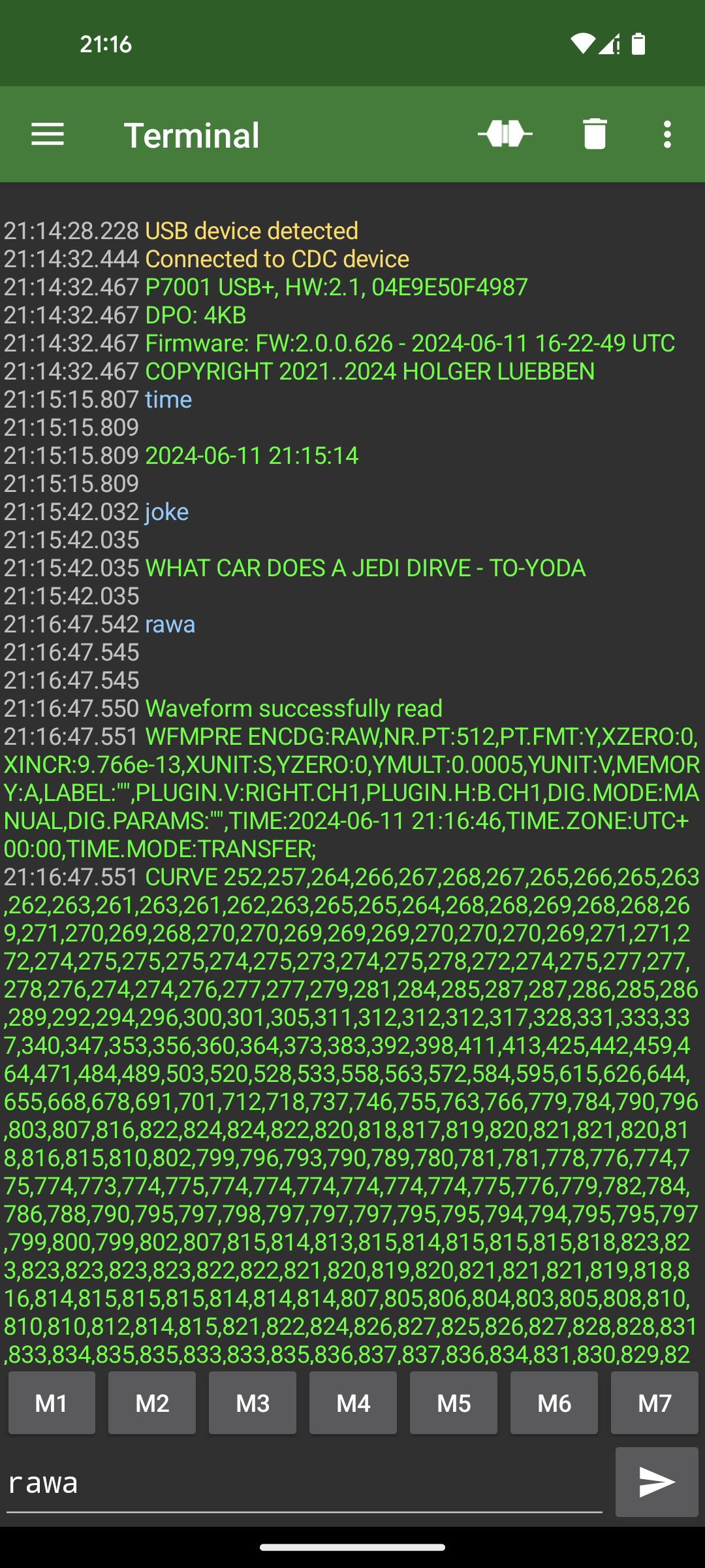
Output Terminal
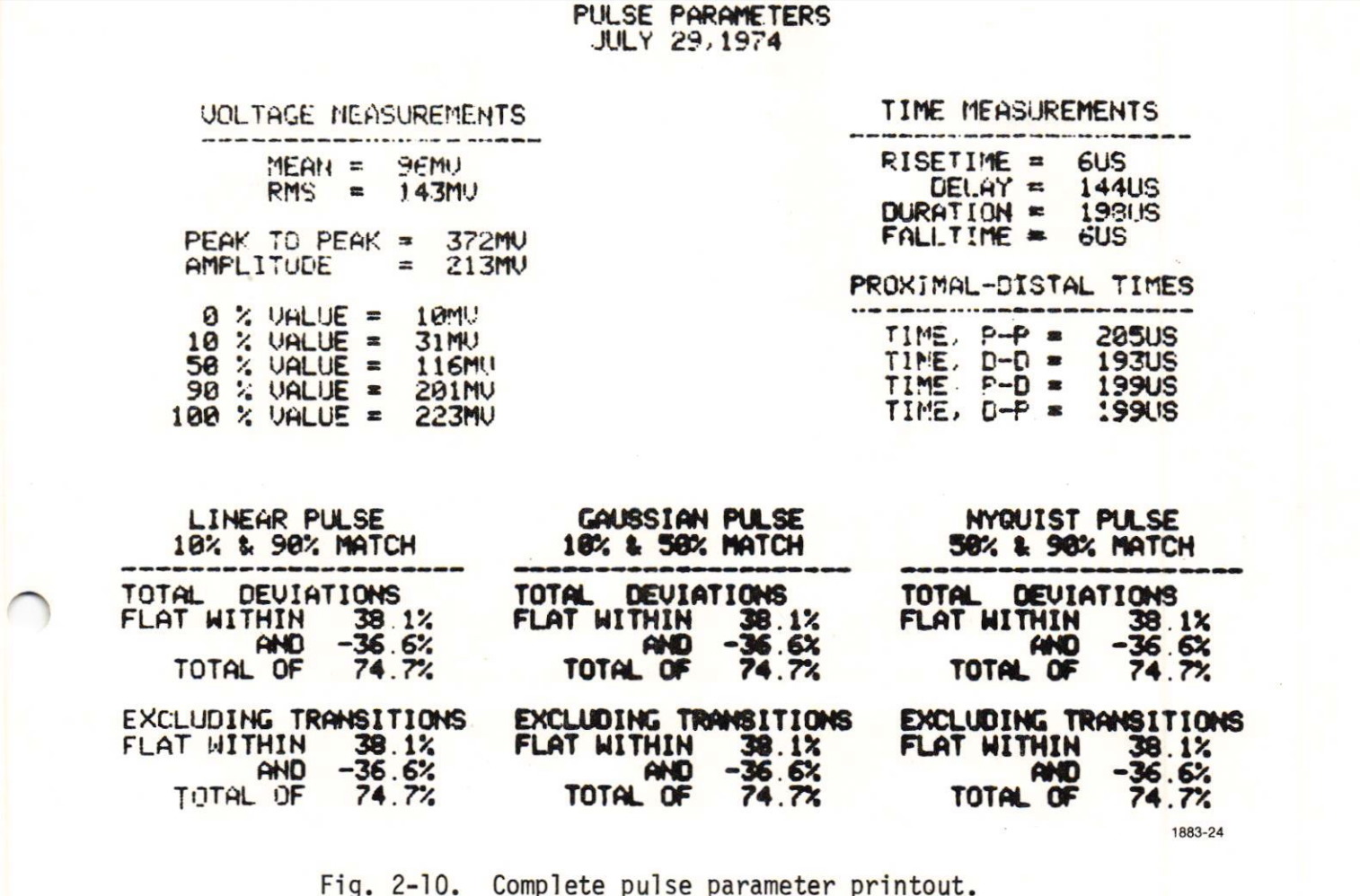
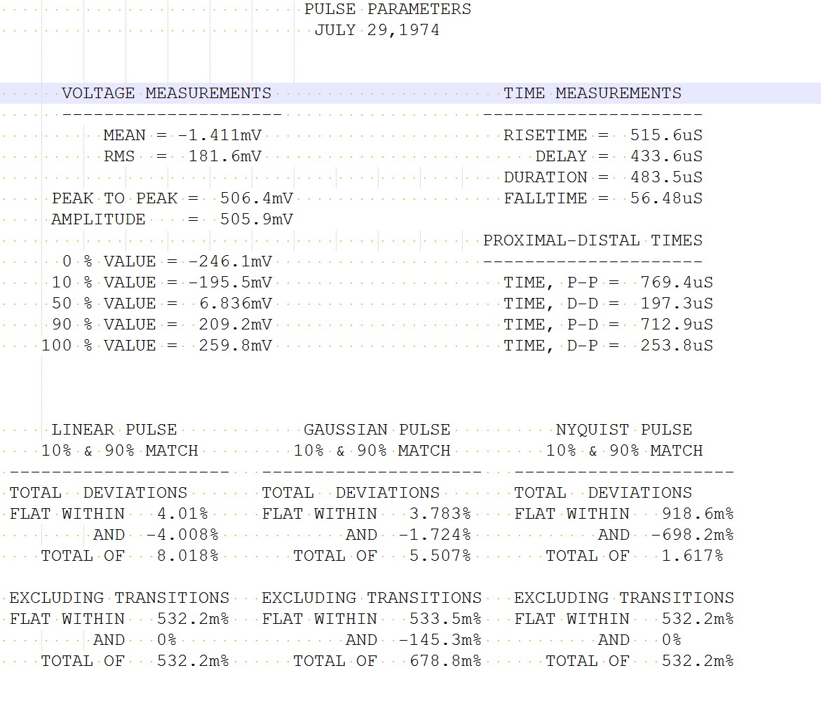
The USB connection will be used by the Interface as an Output Terminal for messages and debug information. One example is the Pulse Parameters Program which prints some Measurement results when the Program Call Buttons 3 or 11 are pressed. Debug Information is sent during firmware development.
The following two pictures are a comparison between the original terminal output vs the modern recreation.
Android Compatibility
The USB interface also works with many Android devices. USB Host mode must be supported and enabled. The interface is automatically detected as a CDC device on Android OS. Baud rate settings are ignored - data transfer is always done at maximum speed. Any terminal program can be used to interact with the P7001 USB Interface.